


Fluxgate vs. Hall-Effect Current Sensors
Source: Probemart 2025-01-08 Views: 2082
Introduction to the principle of the fluxgate current sensor
Fluxgate current sensor principle introduction
Principle: A fluxgate current sensor uses the magnetic flux density and magnetic field strength of a high-permeability magnetic core in the measured magnetic field under saturation excitation by an alternating magnetic field
nonlinear relationship to measure weak magnetic fields. For the ambient magnetic field being measured, this physical phenomenon is like a “gate”; through this “gate,” the corresponding magnetic flux is modulated,
and generates an induced electromotive force. This phenomenon is used to measure the magnetic field generated by a current, thereby indirectly achieving the purpose of current measurement. Essentially,
the fluxgate phenomenon is actually an accompanying phenomenon of the transformer effect and also obeys the law of electromagnetic induction.
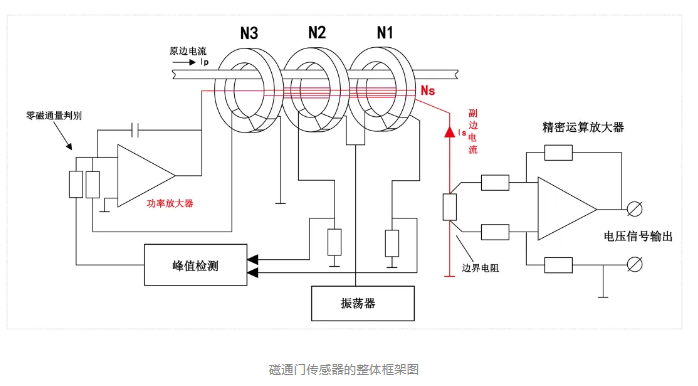
Overall block diagram of the fluxgate sensor
In the magnetic circuit, to construct an equivalent zero-flux magnetic field, current compensation must be applied to the secondary compensation coil. The product of the compensation current and the number of turns of the compensation coil
is proportional to the measured primary current, lp=Ns.ls. In addition, the excitation core and excitation coil form a saturable inductor. Under zero-flux conditions,
detection of the sensor magnetic circuit is based on the change in the inductance value of this inductor.
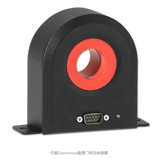
Introduction to the principle of Hall-effect current sensors
Hall current sensor principle introduction
Hall-effect current sensors are divided into open-loop Hall-effect current sensors and closed-loop Hall-effect current sensors.
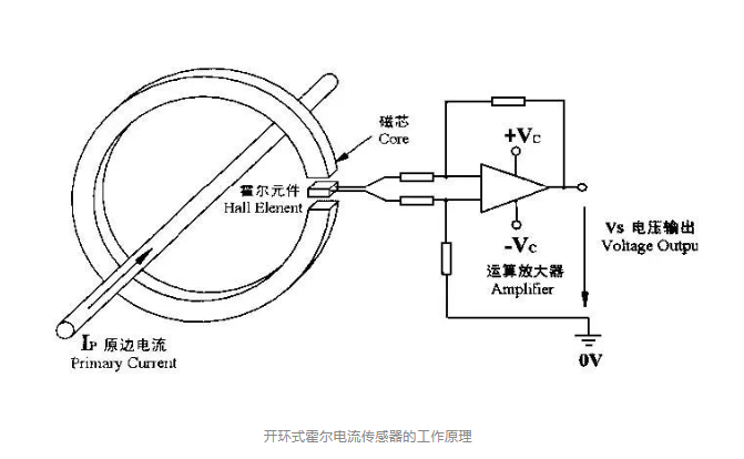
As shown above, an open-loop Hall-effect current sensor consists of a magnetic core, a Hall element, and an amplifier circuit. The magnetic core has an open air gap, and the Hall element is placed at the air gap.
When current flows through the primary conductor, a magnetic field whose strength is proportional to the current magnitude is generated around the conductor; the magnetic core concentrates the magnetic field lines to the air gap,
The Hall element outputs a voltage signal proportional to the magnetic flux density at the air gap, and the amplifier circuit amplifies and outputs this signal. This type of sensor usually outputs
a voltage signal of around +10 V; some sensors convert it to a current signal output to enhance electromagnetic compatibility.

A closed-loop Hall-effect current sensor includes a magnetic core, a Hall element, an amplifier circuit, and a secondary compensation winding. Compared with an open-loop Hall-effect current sensor,
the closed-loop Hall-effect current sensor has an additional secondary compensation winding. It is precisely the secondary compensation winding that greatly improves the performance of the closed-loop Hall-effect current sensor.
the amplifier circuit receives the output of the Hall element and amplifies it into a current signal supplied to the secondary compensation winding; the magnetic field generated by the secondary compensation winding in the magnetic core and
The magnetic field generated by the primary current is equal in magnitude and opposite in direction at the air gap, canceling the primary magnetic field and forming a negative-feedback closed-loop control circuit.

If the secondary current is too small, the magnetic field generated is insufficient to cancel the primary magnetic field, and the amplifier circuit will output a larger current; conversely, the amplifier circuit output current decreases,
thereby maintaining the magnetic field balance at the air gap.
If the primary current changes, the magnetic field balance at the air gap is disrupted, and the negative-feedback closed-loop control circuit likewise adjusts the secondary output circuit so that the magnetic field again reaches
balance. Macroscopically, the air gap will always maintain zero flux and magnetic balance; this is also the origin of the names zero-flux current transformer and magnetic-balance Hall-effect current sensor.

Main differences between fluxgate current sensors and Hall-effect current sensors:
A Hall-effect current sensor detects current by sensing an external magnetic field with a Hall chip; the sensing chip is susceptible to interference from the external environment, generating relatively large zero drift and temperature drift,
In addition, its magnetic core must be cut to form an air gap, and current measurement is performed through changes in magnetic flux in the magnetic core air gap; the presence of the open air gap determines that the Hall-effect current sensor
has inherent deficiencies in measurement accuracy and interference immunity.
Fluxgate current sensing detects current through classical control theory rather than through conventional chip sensing; it is insensitive to the external environment and has essentially no
temperature drift or zero drift. Its magnetic core does not require air-gap cutting, has low magnetic reluctance and high flux stability, and the sensor has high detection accuracy, high sensitivity, and fast response.

As shown in the figure above, Hangzhi's AIT series fluxgate sensors achieve an accuracy of up to 10 ppm (10 parts per million), while Hangzhi's closed-loop Hall-effect current sensors have an accuracy of 0.05%,
whereas open-gap Hall-effect current sensors such as GMW have an accuracy of 1%.

PCIM Europe 2026, Nuremberg: IWATSU and PMK at Booth H7-157
2026-06-15
APEC 2026: 41st IEEE Applied Power Electronics Conference and Exposition
2026-03-15
Semicon China 2026, Shanghai New International Expo Centre (SNIEC)
2026-03-11
WiPDA Asia 2025, Beijing International Convention Center, 15 August
2025-08-06