


Sensors for EMC RF Current Measurement
Source: Probemart 2023-08-18 Views: 1292
Taking automotive electronics EMC testing as an example, reference standard: GB/T18655 Vehicles, boats and internal combustion engines
Radio disturbance characteristics — Limits and methods of measurement for the protection of on-board receivers (equivalent to international standard CISPR25), used to assess the degree of disturbance to in-vehicle radio receivers caused by various electromagnetic disturbances generated by vehicles and their components, and to limit the disturbances in the form of limits
Operating conditions:
Different operating conditions of the DUT can affect emission measurement results. When conducting component/module testing, the DUT shall be operated with reference to actual vehicle conditions, and typical loads and other conditions shall be determined so as to obtain the maximum emission state. Operating conditions shall be specified in the test plan.
In order to ensure that the component/module operates correctly during the test, a peripheral interface unit shall be used to simulate the vehicle installation. According to the specified operating mode, all important sensor and actuator connections on the DUT shall be connected to the peripheral interface unit. The peripheral interface unit shall be capable of controlling the DUT according to the test plan.
The peripheral interface unit may be installed inside or outside the shielded enclosure. If installed inside the shielded enclosure, the disturbance level generated by the peripheral interface unit shall be at least 6 dB lower than the test limit specified in the test plan.
Conducted emissions
Test purpose: to measure continuous disturbances on the EUT power and signal lines
The entire test shall be conducted in an anechoic chamber.
Specific requirements:
The minimum size of the reference ground plane for conducted emissions (voltage method) shall be 1000 mm × 400 mm.
The minimum size of the reference ground plane for conducted emissions (current probe method) shall be 2500 mm × 400 mm.
The reference ground plane for radiated emissions shall have a minimum width of 1 000 mm and a minimum length of 2 000 mm, or be 200 mm larger than each side of the entire equipment, whichever is greater.
— DUT remote ground (vehicle power return line greater than 200 mm): use two artificial networks, one connected to the positive power supply terminal and the other to the power return line.
— DUT local ground (vehicle power return line less than or equal to 200 mm): use one artificial network connected to the positive power supply terminal.
The artificial network shall be mounted directly on the reference ground plane. The housing of the artificial network shall be bonded to the reference ground plane.
The DC resistance between the measurement port ground of the artificial network and the reference ground plane shall not exceed 2.5 mΩ.
The power return line shall be connected to the reference ground plane (between the power supply and the artificial network).
Measurement ports of the artificial network not connected to measuring equipment shall be terminated with a 50 Ω load.
Frequency range: 0.15 MHz to 108 MHz
Test method: voltage method
DUT position: The DUT shall be placed on a non-conductive material with low relative permittivity (εr≤1.4), 50 mm ±5 mm above the reference ground plane.
The DUT enclosure shall not be connected to the reference ground plane unless required to simulate the actual vehicle structure.
Each surface of the DUT shall be at least 100 mm from the edge of the reference ground plane.
When the DUT enclosure is grounded, the grounding point shall be at least 100 mm from the edge of the reference ground plane.
Test harness position:
The power line length Lp between the artificial network connector and the DUT connector shall be 200 mm.
The harness shall be laid in a straight line on a non-conductive material with low relative permittivity (εr≤1.4) at a position 50 mm ±5 mm above the reference ground plane. To minimize coupling between the power line and the input/output leads, the spacing between different types of wires shall be as large as possible (the vertical distance between the input/output leads and the power line connecting the artificial network and the DUT shall be ≥200 mm).
Load position:
The simulated load may be placed close to the reference ground plane (when the simulated load enclosure is bonded to the reference ground plane); or the simulated load may be installed outside the ALSE, with the DUT test harness connected to the reference ground plane through the RF boundary.
Note: When the simulated load is placed on the reference ground plane, the DC power line of the simulated load shall be connected directly to the power supply and shall not pass through the artificial network again.
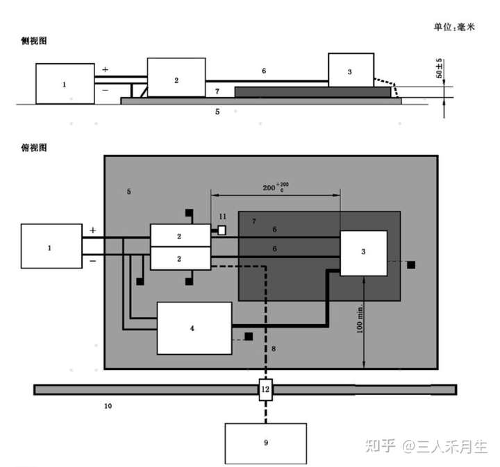
Schematic of remote ground arrangement
| Legend: | |
| 1 — Power supply (may be located on the reference ground plane) | 8 — High-quality coaxial cable (50 Ω), such as double-shielded cable |
| 2 — Artificial network | 9 — Measuring equipment |
| 3 — DUT (the enclosure shall be grounded if required by the test plan) | 10 — Shielded room |
| 4 — Simulated load (the metal enclosure shall be grounded if required by the test plan) | 11—50 Ω load |
| 5—Reference ground plane | 12—Bulkhead connector |
| 6—Power line | 13—Test harness (excluding power line) |
| 7—Low relative permittivity support (εr≤1.4) |
Frequency range: 0.15 MHz to 108 MHz
Test method: current method; emissions are measured with a probe at 50 mm and 750 mm from the DUT.
DUT position:
The DUT shall be placed on a non-conductive, low relative permittivity material (εr≤1.4) at 50 mm ± 5 mm above the reference ground plane.
The DUT enclosure shall not be connected to the reference ground plane unless it is used to simulate the actual vehicle installation.
The DUT shall be at least 100 mm from the edge of the reference ground plane and at least 500 mm from the anechoic chamber walls.
The test plan shall simulate the actual vehicle layout and specify far-end or near-end grounding, use of insulating pads, and the electrical connection between the DUT enclosure and the reference ground plane.

Test harness position:
The test harness shall be 1700 mm long (or as otherwise specified in the test) and shall be placed on a non-conductive, low relative permittivity material (εr≤1.4) at 50 mm ± 5 mm above the reference ground plane.
Unless otherwise specified in the test plan, these test harnesses shall be parallel and close to each other.
Note: If the DUT has multi-port connectors resulting in multiple harness bundles, the test plan shall specify which cables shall be clamped in the current probe for measurement. If no such specification is provided, each harness bundle (connector) shall be measured separately, and then all cables shall be gathered together for measurement.
Generally, the maximum emission position shall be as close as possible to the EUT connector. When the EUT is fitted with a metal-shell connector, the probe shall clamp the cable closest to the connector shell but shall not clamp the connector shell. The EUT and all parts of the test setup shall be at least 100 mm from the edge of the ground plane.
Note: Some additional tests, including those in which only the positive power line and/or negative power line is encircled by the probe, shall be specified in the test plan. The limits for this test setup shall be specified in the test plan.

PCIM Europe 2026, Nuremberg: IWATSU and PMK at Booth H7-157
2026-06-15
APEC 2026: 41st IEEE Applied Power Electronics Conference and Exposition
2026-03-15
Semicon China 2026, Shanghai New International Expo Centre (SNIEC)
2026-03-11
WiPDA Asia 2025, Beijing International Convention Center, 15 August
2025-08-06