


Voltage Measurement under High Common-Mode Interference: Optically Isolated Probes
Source: Probemart 2024-12-12 Views: 1291
Voltage measurement solution under high common-mode interference - optically isolated probe(Background)
In recent years, with the rapid rise of new energy, power-electronics semiconductor devices in fields such as photovoltaics, wind power generation, electric vehicles, and transportation have developed rapidly,
In technical terms, power-electronic devices are developing toward higher voltage, faster switching frequency, and lower loss, and the accompanying high-voltage, high-frequency technology
the problems brought about are also becoming increasingly difficult during R&D. Due to the complex electromagnetic-field environment caused by the high frequency/high voltage during switching-device operation, in the field of electronic measurement
it is also facing the impact of increasingly severe common-mode interference signals; then, in high-voltage/high-frequency environments, how do we ensure measurement accuracy?
What is common-mode interference
Interference present on any two power supply lines can be expressed as common-mode interference and differential-mode interference.
Common-mode interference is transmitted between a wire and ground (chassis), is an asymmetric interference, and is defined as the unwanted potential difference between any current-carrying conductor and reference ground;
Differential-mode interference is transmitted between two wires, is a symmetric interference, and is defined as the unwanted potential difference between any two current-carrying conductors.
Under normal circumstances, common-mode interference has large amplitude and high frequency, can also radiate through wires, and causes greater interference. Differential-mode interference has small amplitude and low frequency and causes less interference.

Causes of common-mode interference
l Common-mode interference voltage is introduced from the power grid.
l Radiated interference (such as lightning, equipment arcs, nearby radio stations, and high-power radiation sources) induces common-mode interference on signal lines; the reason is that an alternating magnetic field generates an alternating current,
The ground-neutral loop area is not the same as the ground-live loop area, and different impedances of the two loops and other causes result in different current magnitudes.
Ground voltages are different; simply put, the potential difference creates common-mode interference. l
l Common-mode interference caused by the equipment's internal wiring on the power line.

Waveform of the common-mode interference signal measured by the oscilloscope
How can the effect of common-mode interference on measurement be avoided
l Use shielded twisted pairs and ensure effective grounding
l Shielding must also be considered in locations with strong electric fields
l During routing, keep away from high-voltage lines; high-voltage power lines and signal lines must not be bundled together
l Do not share the same power supply with high-frequency switching equipment and other interference-prone equipment
l Use a linear regulated power supply or a high-quality switching power supply(low ripple interference)
l Use differential or isolated circuits
In electronic measurements, we often use differential probes to reduce the effect of common-mode interference on circuit measurements.
Is there a better method than differential probes?
Although differential probes can reject common-mode noise, they are limited by high frequency; generally, the high-frequency rejection capability of differential probes is not very high. By contrast, the optical isolation method,
Because the optical isolation method connects the front end to the back-end circuit via an optical signal, it completely isolates the influence of possible common-mode interference signals during transmission,
Therefore, the common-mode rejection capability (CMRR) of the optically isolated method is not affected by voltage and frequency.

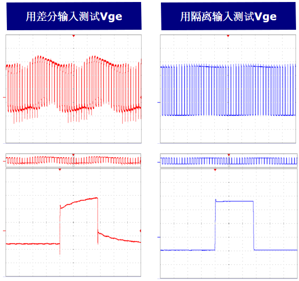
Comparison of Vge waveforms measured with an optically isolated probe and a differential probe on the high-side arm of a VVVF variable-frequency drive
In high-voltage and high-frequency switching environments, such as the VVVF variable-frequency drive of high-speed trains, the gate voltage Vge of the high-side switching device,
Due to common-mode interference and floating ground, the waveform is severely distorted, and the amplitude fluctuates significantly (due to the floating ground).
In analyzing the problem, it is difficult to determine whether it is a measurement issue or a driver-circuit issue. The optically isolated probe can solve this problem effectively.
In addition, in high-voltage environments, besides the common-mode interference problem, there are also personnel and equipment safety issues; complete electrical isolation is, for ensuring personnel and equipment safety,
a sufficient condition. At the same time, the ability to perform remote measurement is also a test condition that needs to be considered.

Application areas of optically isolated probes
l Grid GIS UHV air circuit breaker
l High-speed rail/on-board/ship high-voltage equipment
l Wind turbine installation and commissioning
l High-voltage inverter measurement
l Semiconductor equipment
l Medical equipment
l High-energy physics experiments

Introduction to the IWATSU high-voltage optically isolated probe SE6000
SE-6010 (left) SE-6000 (right)
Isolation unit (transmitting side) Isolation amplifier (receiving side)

Unique advantages:
l Excellent common-mode rejection performance and high-quality floating testing
l Measurement at remote locations (switchgear, transportation equipment, etc.)
l Lightning impulse testing, live testing, etc., suitable for a wide range of applications
Operating instructions for the IWATSU high-voltage optically isolated probe SE6000
The IWATSU SE6000 optically isolated probe requires a separate high-voltage probe for front-end high-voltage signal input; its voltage rating is determined by the front-end high-voltage probe.
The main body of the SE6000 optically isolated probe consists of two parts: the isolation unit SE6011 and the isolation amplifier SE6000.
The isolation unit SE6011 connects directly to the high-voltage probe to form the front-end signal acquisition end of the measurement; after A/D conversion, the signal is transmitted over a 3-50 m (custom 200 m)
optical fiber that isolates and transmits the signal to the isolation amplifier SE6000; the isolation amplifier SE6000 then transmits the analog signal to the oscilloscope via D/A conversion
or other measurement equipment. The entire process completes the measurement process of electrical-to-optical conversion followed by optical-to-electrical conversion, achieving electrical isolation.
and ensured the reliability of our testing under high common-mode interference.
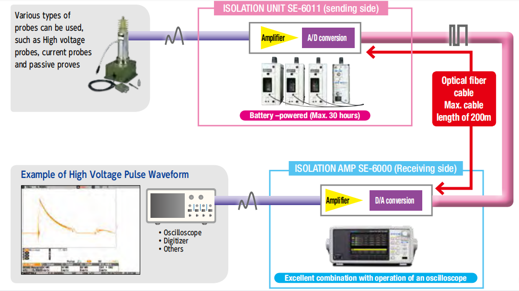
IWATSU high-voltage optically isolated probe SE6000 system wiring method

PCIM Europe 2026, Nuremberg: IWATSU and PMK at Booth H7-157
2026-06-15
APEC 2026: 41st IEEE Applied Power Electronics Conference and Exposition
2026-03-15
Semicon China 2026, Shanghai New International Expo Centre (SNIEC)
2026-03-11
WiPDA Asia 2025, Beijing International Convention Center, 15 August
2025-08-06