


Inside a Power-Device Double-Pulse Test Platform
Source: Probemart 2026-05-26 Views: 209
Double-pulse testing is an important means of characterizing the dynamic characteristics of power semiconductor devices and is applicable to various power devices, includingMOSFET、IGBT、Diode、SiC MOSFET、GaN HEMTsAt the same time, this test is performed in all stages such as device R&D, device production, and system application. The test results provide a strong guarantee for device characteristics and quality, as well as for the performance and safety of power converters; it can be said to accompany the critical moments in the life of power devices.
To do a good job, one must first sharpen one's tools. Having a double-pulse test platform is the first step toward obtaining correct evaluation results. This article will address the challenges of building a double-pulse platform; take a look.
Double-pulse test platform architecture
The figure below shows the architecture of the double-pulse test platform. It is not complex and mainly includes:test board, high-voltage power supply, auxiliary power supply, signal generator, load inductor, oscilloscope, voltage probe, and current probe.

1.Test board
The test board is the core of completing double-pulse testing. It is generally a half-bridge circuit, and sometimes a topology based on the actual system application is also used. Its main components include the bus capacitor and the drive circuit. The bus capacitor provides a stable bus voltage and the required current for the test process, and the drive circuit controls the device to complete switching actions to implement the double-pulse process.
The quality of the test board directly affects the correctness of the evaluation results.The test board must first ensure that no abnormal waveforms occur under error-free measurement, such as voltage spikes exceeding the device withstand voltage rating, unexplained oscillations, bridge-arm short circuits, etc.; otherwise, such test results are of no value. For test requirements serving device selection for system applications, the actual converter circuit board can be directly selected as the test board, and such test results can be directly used for circuit design. As device switching speeds become increasingly faster, higher requirements are also placed on test board performance, such as loop inductance and the drive circuit.
2.High-voltage power supply
The high-voltage power supply charges the bus capacitor on the test board before the test begins, thereby setting the test voltage. The bus capacitor generally has a large capacitance, ranging from tens ofuFto a fewmFare unequal, which requires the high-voltage power supply to have strong voltage regulation capability for capacitive loads. In double-pulse testing, the test voltage generally does not exceed the withstand voltage of the device, so the voltage output capability of the high-voltage power supply can be determined according to the voltage rating of the device under test. At the same time, the same double-pulse test platform is often used to test devices of different voltage ratings, which requires the output voltage accuracy of the high-voltage power supply to meet the test requirements.
In addition, in double-pulse testing, the test current is provided by the fully charged bus capacitor, and the high-voltage power supply does not provide energy during the test. Therefore, a lower-power model can be selected for the high-voltage power supply, which can reduce cost on the one hand and reduce noise on the other.
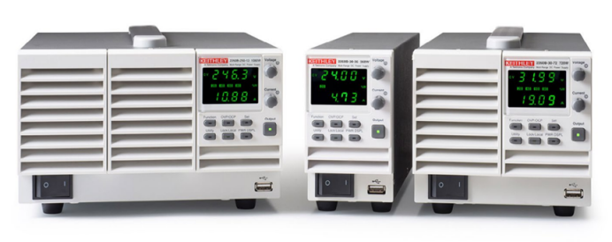
The high-voltage power supply can be a Tektronix Keithley2260B-800-2DC power supply
3. Auxiliary power supply
The auxiliary power supply provides power to the driver circuit on the test board; the required voltage is generally within20Vand the required power is generally within20WAt the same time, for a test board where both the high-side and low-side switches are switching devices, a dual-channel output auxiliary power supply can be selected to supply the driver voltages for the high-side and low-side switches separately; for double-pulse testing of a three-level circuit, a three-channel output auxiliary power supply can be selected to supply the driver voltage for each device separately. The advantage is that the reliability of the test circuit can be improved, and a fault in one driver circuit will not affect other driver circuits.
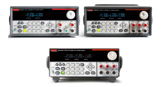
For the auxiliary power supply, a Tektronix Keithley 2220 / 2230 / 2231series DC power supply
4. Signal generator
The function of the signal generator is to send double-pulse signals to the driver circuit on the test board to complete the double-pulse test. Since the frequency of the double-pulse signal required for the test is not high, and its rise and fall speed has little effect on the test, the most basic generator model available from each manufacturer can be selected.
However, it should be noted that after modification, the double-pulse test platform can also perform multi-pulse testing, short-circuit testing, avalanche testing, and open-loop power supply testing; in these cases, more than one control signal is often required. Therefore, when building a double-pulse test platform, a dual-channel output signal generator can be selected to improve flexibility.
At the same time, during double-pulse testing, the pulse width and interval of the double-pulse signal need to be continuously adjusted according to the test conditions. Old-style signal generators require manual waveform entry and editing or PC programming, which is very inconvenient.To address this problem, one can select the TektronixAFG31021(single-channel) orAFG31022(Dual-channel) signal generator; its built-in double-pulse testingappcan quickly implement double-pulse signal setup.

AFG31000series arbitrary waveform function generator
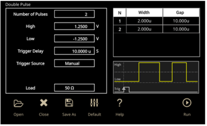
double-pulse testing app interface
5. Oscilloscope
Oscilloscopes are used to acquire waveforms during device switching, including at least the gate-drive waveform, terminal voltage waveform, and terminal current waveform; a 4-channel oscilloscope can therefore be selected. In addition, sometimes the high-side and low-side devices must be tested simultaneously; in this case, an 8-channel oscilloscope can be selected, easily handling multi-channel signal acquisition.
When selecting an oscilloscope, bandwidth, resolution, noise, sampling rate, etc. must also be considered. Conventional devices have slow switching speeds and impose low requirements on oscilloscopes. However, with the emergence of increasingly advanced power devices featuring wider voltage and current ranges and faster switching speeds, higher requirements are placed on oscilloscopes used for double-pulse testing.
The 1 GHz versions of the Tektronix MSO5B and MSO6B series oscilloscopes can be selected; they meet the bandwidth requirements for high switching speeds. Their 12-bit ADC significantly improves measurement accuracy and reduces measurement noise, with the most notable effect on high-voltage, high-current devices. In addition, MSO5B and MSO6B series oscilloscopes offer three configuration options: 4-channel, 6-channel, and 8-channel.
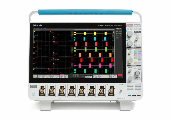
Tektronix MSO5B series high-resolution multi-channel oscilloscopes
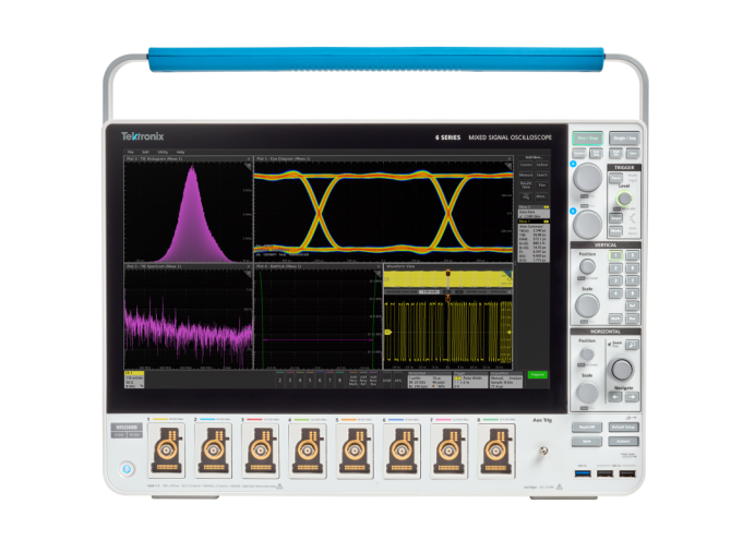
Tektronix MSO6B series high-resolution low-noise oscilloscopes
6. Voltage probe
Voltage probes are used to measure the gate-drive voltage waveform and terminal voltage waveform of the device under test.
10× passive probe:The bandwidth is up to 1 GHz, and the attenuation ratio is low; using a passive probe can provide accurate gate-drive voltage waveforms. Because it is a passive probe, it can only be used to measure the gate-drive voltage of the low-side device. It can also be used to measure the terminal voltage of devices below 200 V and can obtainthe most accurate terminal voltage measurement results. During use, attention must also be paid to the influence of the ground lead and impedance matching, and it can only be used for low-side measurement.
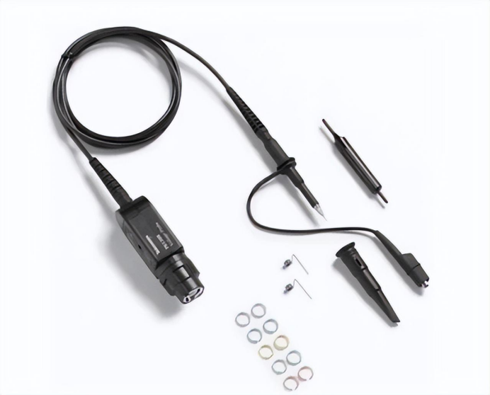
Tektronix 10X passive probe
When using a 10× passive probe to measure the gate-drive voltage, pay attention to the influence of the ground lead and impedance matching; for details, refer to the previous recommendations below.
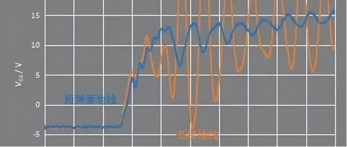
High-voltage single-ended probe:Maximum measurement range up to 2500 V; maximum bandwidth up to 800 MHz; enables the most accurate terminal voltage measurement results. During use, the influence of the ground lead and impedance matching must also be considered, and it can only be used for low-side measurements.

High-voltage differential probe:It has a differential input, so it can be used for high-side testing; however, because its CMRR is not high enough, its measurement correctness and accuracy are insufficient for accurate device characteristic analysis. It is an active probe, and its input impedance is larger than that of a 10× passive probe, making it safer for the oscilloscope when the device under test is damaged. Because its attenuation ratio is large, generally above 50×, the measured gate-drive voltage waveform has higher noise and lower accuracy. Because its lead length at the tip is relatively long, it is susceptible to interference, resulting in erroneous measurement results.

Its maximum measurement range is up to 6500 V; differential input; can be used for high-side device measurements. For the same reasons as when measuring gate-drive voltage, its test accuracy is poorer than that of passive probes, and its bandwidth is not high enough. Its maximum bandwidth reaches 200 MHz, which cannot meet the requirements for accurate dynamic characteristic testing of high-speed devices such as SiC and GaN devices.
Optically isolated probe:Bandwidth up to 1 GHz; minimum attenuation ratio only 1×; CMRR up to -90 dB at 1 GHz; an optically isolated probe can obtain the most accurate gate-drive voltage waveform, and it is currently the best tool for measuring high-side gate-drive voltage waveforms.
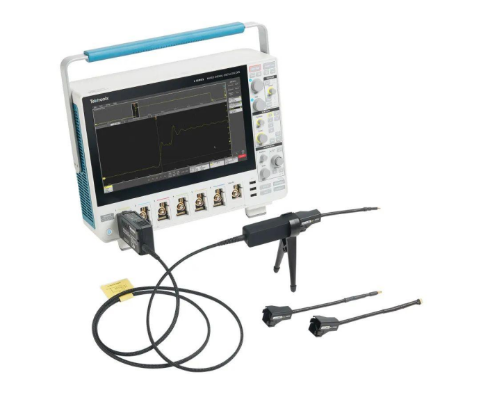

7. Current probe
Rogowski coil:Measurement range from tens of amperes to several thousand amperes with no saturation problem; can only measure AC current and cannot measure DC current; it is well suited for measuring device switching/reverse-recovery characteristics. A Rogowski coil can be slipped directly around the device to measure current, such as the pins of discrete devices, the terminals of power modules, and the bond wires of power modules; this method does not damage the main power circuit and thus does not affect device characteristics. However, its maximum bandwidth is only 30 MHz, so it cannot accurately measure the current of high-speed devices.
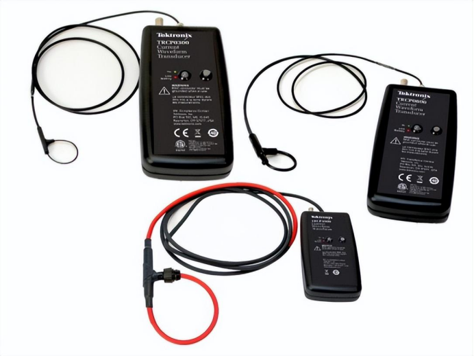
Coaxial resistor:Maximum bandwidth up to above 1 GHz; the special mounting method introduces relatively small parasitic inductance into the power loop; measurement accuracy is high; accurate device turn-off current can be obtained; it is especially the preferred choice for SiC and GaN devices.

Reprinted from Tektronix

PCIM Europe 2026, Nuremberg: IWATSU and PMK at Booth H7-157
2026-06-15
APEC 2026: 41st IEEE Applied Power Electronics Conference and Exposition
2026-03-15
Semicon China 2026, Shanghai New International Expo Centre (SNIEC)
2026-03-11
WiPDA Asia 2025, Beijing International Convention Center, 15 August
2025-08-06