


Negative Current in GaN Double-Pulse Testing
Source: Probemart 2025-01-08 Views: 1496
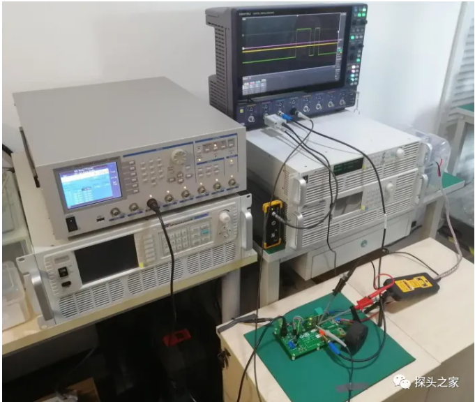
Test platform: GaN
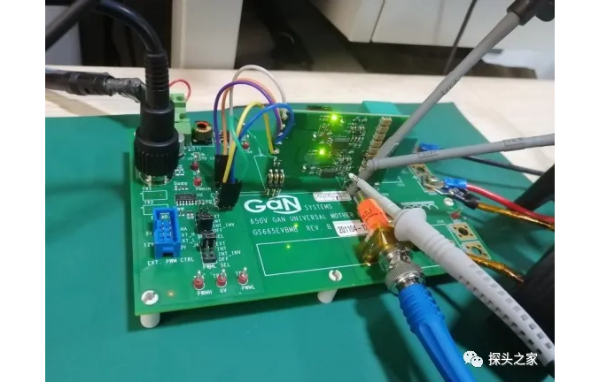
Device: GaN SYSTEM GS66508T GaN
Evaluation board: Broadcom ACPL-P346
Pulse signal source: IWATSU DG8000, 6 channels
Oscilloscope: IWATSU DS-8108, 8 channels, 1 GHz bandwidth, 12-bit resolution
Power supply: Quantian SPV600VDC4000W, DC 600 V, 4000 W
High-voltage differential probe: PMK BUMBLEBEE (Bumblebee), 2000 VRMS, 400 MHz bandwidth
Current probe: T&M SDN-414-10, 0.1 Ω, 2 GHz bandwidth
Rogowski coil IWATSU SS-286, 30 MHz bandwidth, 1200 A
1. Experimental problem:
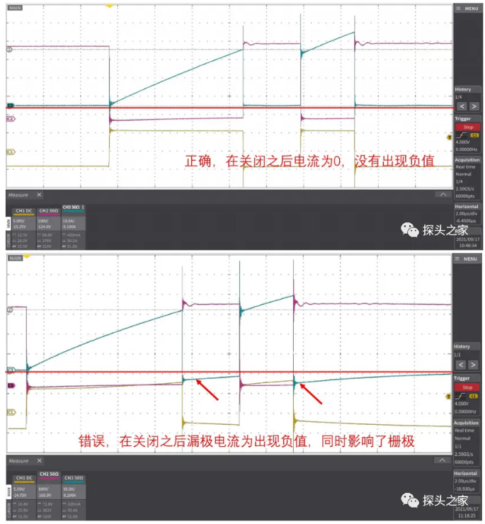
In the double-pulse test, when the device turns off, the current probe detects a negative current, which is inconsistent with the theoretical result.
The experimental waveforms are as follows:
2. Cause analysis:
First, to rule out whether the negative current is actually generated, a Rogowski coil was added in the experiment to measure the IC current.

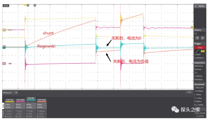
The experimental results show that at the turn-off instant, the Rogowski coil current is 0 and the coaxial shunt current is negative.Since the Rogowski coil's operating principle
is a coil mutual-inductance operating principle, the greatest advantage of the Rogowski coil over the coaxial shunt is that, through electrical isolation,
it reduces the impact on the measurement loop. Therefore, this IC current measurement result from the Rogowski coil should be more reliable.
Further measures to reduce the influence of external measurements on the loop: use only the current probe, remove the gate Uge probe and Uce probe, and observe only the current result.
Experimental results:

The shunt current is no longer negative; it can be confirmed that the Uge and Uce probes affected the experimental results of the main circuit.
Further narrow down the scope to find the real cause of the negative current. Experiment with the Uce probe and 2 current probes connected.
Experimental results:

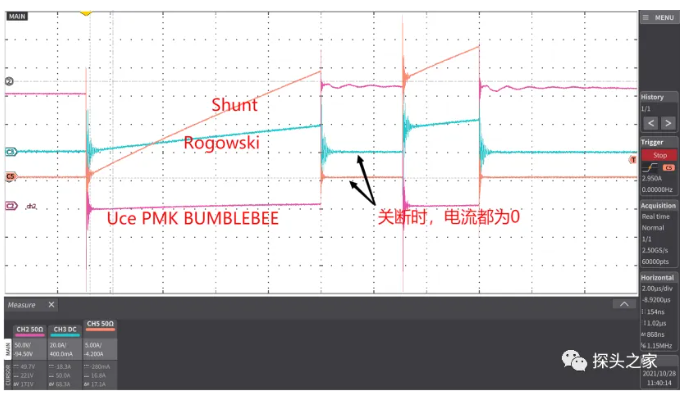
Therefore, the Uce differential probe is not the cause of the negative current.
Next, examine again the experiment with the Uge probe and two current probes connected.
Experimental results:

It can be confirmed that the measurement by the gate probe Uge affected the measurement circuit.
3. Experimental conclusions
Cause analysis: In the experiment, the gate probe used was a PMK passive probe. Because the passive probe ground is not isolated, it shares a common ground with the shunt in the oscilloscope connection.
This formed a ground loop; thus, when the device turns off, the energy in the stray inductance is released through the common-ground loop and via the shunt, forming a negative current.
Therefore, if we use a differential probe, we can eliminate the effect of Uge on the measurement circuit.
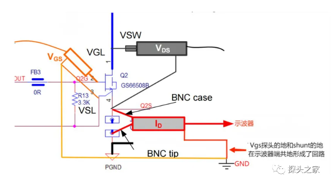
To verify our conclusion, measure the Uge voltage with a differential probe. Because the negative terminal of the differential probe is isolated, this avoids the negative current generated by the loop formed by common grounding.
Test results:

The experimental results show that after differential isolation, the turn-off current of the shunt becomes 0. The cause of the negative current has been found and resolved.
http://www.probemart.com/

PCIM Europe 2026, Nuremberg: IWATSU and PMK at Booth H7-157
2026-06-15
APEC 2026: 41st IEEE Applied Power Electronics Conference and Exposition
2026-03-15
Semicon China 2026, Shanghai New International Expo Centre (SNIEC)
2026-03-11
WiPDA Asia 2025, Beijing International Convention Center, 15 August
2025-08-06